algorithmic modeling for Rhino
dome stresses
hi there,
for understanding the karamba shell components i investigate load on a simple dome (half a sphere).
i want to figure out where to place tension elements (like tension cables or fibres)
one would expect to put them into the lower part of the dome ( just self weight for simplicity)
http://shells.princeton.edu/images/BFigure8.png
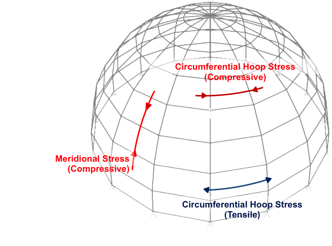
i have problem to understand the renderings of the shellView component.
could someone explain difference between princ. stress 1/2 and why stress is also displayed in the top section of the dome (princ.stress 1 plot)
maybe because its not a rotated catenary ?
is it also possible to get out vectors of the shellView component.
thank you !
Views: 1113
- Attachments:
-
-
 dome karamba.gh, 28 KB
-
Replies to This Discussion
-
Permalink Reply by Karamba3D on
-
Hi Pyrit,
the principal stresses are the minimum and maximum normal in-plane stresses in a point of a shell structure.
Why should there be no stress in the top section of the shell?
Use the 'Principal Stress Directions on Shells'-component to get vectors as result.
Best,
Clemens
-
-
Permalink Reply by pyrit on
-
So one more question,
if i want to strenghten a shell structure with rod like elements ( i would like to investigate reed )
i should use the principal stressLinesOnShells component and prinicpalForceDirectionsOnShells component to figure out their best location. for the most simple cases its clear what compression and what tensile is but is there exact way to tell (N1 or N2)
thy !
-
-
-
The principal stress lines on shells indicate the best orientation for reinforcing elements.
If bending moments are small you could use the directions and values of the first principal in-plane normal forces: the former is returned by the 'PrincipalForceDir'-component, the latter via the 'Shell Forces'-component.
Best,
Clemens
-
About
Welcome to
Grasshopper
Translate
Search
Photos
Videos
© 2025 Created by Scott Davidson.
Powered by
![]()