algorithmic modeling for Rhino
Mapping a shape between two triangles
Hi,
I've been trying to solve this by several approaches but couldn't fnd a way. I have a number of triangles with different proportions, and I'd like to map onto each one a reference shape I've drawn around a reference triangle.
The problem seems to be that the target triangles are generated by the three vertices as trimmed surfaces, and so if I use a bbox, the resulting box is not what I'd expect. Please see images attached.
All the examples I've found use four-sided cells. Is there any way to do this with triangles?
Views: 5273
Replies to This Discussion
-
Permalink Reply by Mateusz Zwierzycki on
-
This is probably because bsplines are referenced by control points not by actual points on curve position. Here is a simple workaround.
- Attachments:
-
-
 remap curve well.gh, 8 KB
-
-
-
Permalink Reply by San Tuta on
-
Thanks a lot for the reply. The workaround didn't work, though. The error message says "insufficient vertices for a curve" (see attached). It seems that the shape gets mappeed onto the triangle. I tried swaping the shape and the reference triangle, but it didn't work either. Any ideas?
Cheers.
- Attachments:
-
-
 result.jpg, 104 KB
-
-
-
-
that is because it works only if curve is completely inside triangle...
-
-
Permalink Reply by Jacek Jaskólski on
-
I think you just need to perform some affine transformations.
Here's my attempt:
Definition attached.
It works by combining orienting, scaling & skewing. It was my first intuitive approach to this, so it's unnecesarily complicated. There's probably a much easier way to achieve this (anyone?).
The example above is a planar case, but the definition will "morph" any geometry, you'd just need to adjust "height" scaling, as it is now proportional to the distance from Pt(0) to Pt(1).
- Attachments:
-
-
jj_affline_transform.gh, 14 KB
-
-
-
-
I've just realised the first sentence in my previous post came out silly, since I first heard about affine transformations just minutes ago when I read the wikipedia article, and I'm not going to pretend I understand the math described in it ;-) So if anyone more familiar with the science behind this would like to clarify, please do!
-
-
Permalink Reply by Yoann Mescam (Systemiq) on
-
I answered to a similar problem there.
Perhaps it can help. Jacek's solution looks nicer though.
-
-
Permalink Reply by Daniel Piker on
-
It seems like barycentric coordinates might be useful for this.
It should be possible to put together a GH definition from the description here : http://mathworld.wolfram.com/BarycentricCoordinates.html
-
-
-
Hi Daniel,
I understand how barycentric coordinates could be used to map points from one "triangle-space" to another. Do you think the concept could be useful to define the general transformation matrix also?
I mean what I would like to do is to define T as a 4x4 transformation matrix such that:
A*T=B
where A is the collection of three reference points and B - the target points.(or ideally a solution for the mapping between two arbitrary tetrahedra)
Having that it could be used directly to "morph" any geometry from one "system" to another.
I tried something using the method described here, but it seems I'm lacking some fundamental understanding of how such a matrix should be constructed, because I'm getting nonsense results.
EDIT: unbelievably bad luck, stackoverflow is having a maintenance pause right now.
google cache link here. -
-
-
Hi Jacek, interesting idea.
I think yes, in 3d it would make more sense to work with barycentric coordinates on tetrahedra, rather than just triangles.
The wikipedia page says this is just a question of inverting a 3x3 matrix.
So then you'd have a weight to multiply each of 4 points by and adding the results would give you your point relative to a new tetrahedra.
I'd probably try making a 2d version first though.
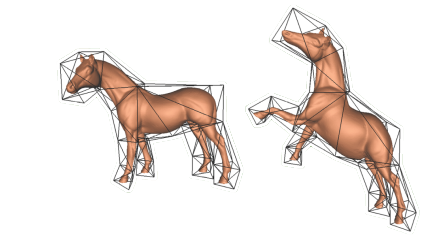
I think this sort of thing is quite widely used in animation and simulation. It would be nice because you can make a simple system of spring tetrahedra, and use it to simulate physical deformations of a much more detailed mesh, something like this
-
-
-
Ok, so barycentric point mapping in 2d is easy. Attached a definition if anyone is interrested. It follows the logic of the wikipedia article mentioned above.
I can see how this can be extended to 3d "tetrahedral" mapping .But I still fail to grasp how to obtain the general transformation matrix using barycentric coordinates. I'd like to be able to use it directly to transform any geometry at one go, by pluging the data to a Transform component, and not point-by-point.
I mean if we were to transform a mesh this way, then no problem - you just need to transform each point and recreate the mesh. But what about other types of geometry?
- Attachments:
-
-
-
I finally managed to put together a very simple VB.Net script which does it:
Definition attached. Unfortunately it works only on Rhino5, because it uses the matrix class and Rhino4 seems to have a problem with that.
Now when I'm writing this I realise that this can be easily avoided by substituing the matrix type with rhino.geometry.transform type and it should run on 4.0. I've started off with the 2d case using a 3x3 matrix, so that's why I needed the broader class.
Thanks to Giulio & Andrew for helping me understand the matrix syntax!
- Attachments:
-
-
tetrahedral mapping.gh, 13 KB
-
-
-
-
Rhino4.0 compatible version of the above definition attached.
@Daniel - I'd like to give this def. a test drive, do you perhaps have a model of a horse? ;-)
- Attachments:
-
-
tetrahedral mapping 2.gh, 13 KB
-
-
About
Welcome to
Grasshopper
Translate
Search
Photos
Videos
-
Scaling Tower
Added by Parametric House 0 Comments 0 Likes
-
Field Trap
Added by Parametric House 0 Comments 0 Likes
-

Subd Bridge
Added by Parametric House 0 Comments 0 Likes
© 2024 Created by Scott Davidson.
Powered by
![]()