algorithmic modeling for Rhino
Search Results - %E9%84%8211%E9%80%89%E4%BA%94app%7C-wn4.com%7C-11%E9%80%89%E4%BA%94%E5%A5%87%E8%91%A9%E9%80%89%E5%8F%B7%E6%B3%95-w3b2s1-2023%E5%B9%B43%E6%9C%8819%E6%97%A57%E6%97%B643%E5%88%8631%E7%A7%92-6ay7xb3tp.com
- Blog Post: Unfolding polygons definition
-
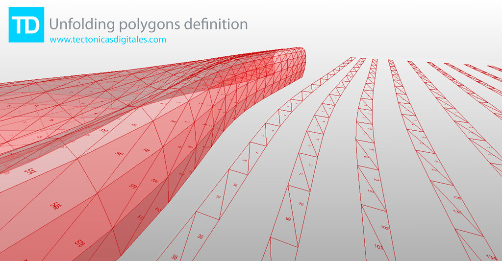
- Added by Francisco Calvo at 11:08am on February 8, 2010
- Topic: Smartgeometry 2012 - a Call for Workshop Cluster proposals
- nowledge, tools, materials and machines. The Clusters provide a focus for workshop participants working together within a common framework. Clusters provide a forum for the exchange of ideas, processes and techniques and act as a catalyst for design resolution. The Workshop is made up of ten Clusters that respond in diverse ways to the sg2012 Challenge Material Intensities. The Call for Clusters is now open to proposals which respond in innovative ways to this year's challenge. Deadline: September 19 2011 More information can be found here: http://smartgeometry.org/index.php?option=com_content&view=article&id=129&Itemid=146 sg2012 takes place from 19-24 March 2012 at EMPAC (http://empac.rpi.edu/) and is hosted by Rensselaer Polytechnic Institute in Troy, upstate New York USA. The Workshop and Conference will be a gathering of the global community of innovators and pioneers in the fields of architecture, design and engineering. The event will be in two parts: a four day Workshop 19-22 March, and a public conference beginning with Talkshop 23 March, followed by a Symposium 24 March. The event follows the format of the highly successful preceding events sg2010 Barcelona and sg2011 Copenhagen. sg2012 Challenge Material Intensities Simulation, Energy, Environment Imagine the design space of architecture was no longer at the scale of rooms, walls and atria, but that of cells, grains and vapour droplets. Rather than the flow of people, services, or construction schedules, the focus becomes the flow of light, vapour, molecular vibrations and growth schedules: design from the inside out. The sg2012 challenge, Material Intensities, is intended to dissolve our notion of the built environment as inert constructions enclosing physically sealed spaces. Spaces and boundaries are abundant with vibration, fluctuating intensities, shifting gradients and flows. The materials that define them are in a continual state of becoming: a dance of energy and information.Material potential is defined by multiple properties: acoustical, chemical, electrical, environmental, magnetic, manufacturing, mechanical, optical, radiological, sensorial, and thermal. The challenge for sg2012 Material Intensities is to consider material economy when creating environments, micro-climates and contexts congenial for social interaction, activities and organisation. This challenge calls for design innovation and dialogue between disciplines and responsibilities.sg2010 Working Prototypes strove to emancipate digital design from the hard drive by moving from the virtual to the actual in wrestling with the tangible world of physical fabrication. sg2011 Building the Invisible focused on informing digital design with real world data. sg2012 Material Intensities strives to energise our digital prototypes and infuse them with material behaviour. They have the potential to become rich simulations informed by the material dynamics, chemical composition, energy flows, force fields and environmental conditions that feed back into the design process. More information can be found at http://www.smartgeometry.org…
- Added by Shane Burger at 1:05pm on August 9, 2011
- Comment on: Topic 'Heat Island Effect'
- umbrella of Urban Heat Island (UHI) and I am going to try to separate them out in order to give you a sense of the current capabilities in LB+HB. 1) UHI as defined as a recorded elevated air temperature in an urban area: If you have access to epw files for both an urban area and a rural area, you can use Ladybug to visualize and deeply explore the differences between the two weather files. Ladybug is primarily a tool for weather file visualization and analysis and it can be very helpful for understanding the consequences of UHI on strategies for buildings or on comfort. This said, if you do not have both rural and urban recorded weather data or you want to generate your own weather files based on criteria about urban areas (as it sounds like you want to do), this definition might not be so helpful. 2) UHI defined by air elevated air temperature but viewed as a computer model-able phenomenon resulting primarily from urban canyon geometry, building materials, and (to a lesser degree) anthropogenic heat: This definition seems to fit more with they type of thing that you are looking for but it is unfortunately very difficult and computationally intensive such that we do not currently have anything within Ladybug to do this right now. I can say that the state-of-the art for this type of modeling is an application called Town Energy Budget (TEB) and this is what all of the advanced UHI researches that I know use (http://www.cnrm.meteo.fr/surfex/spip.php?article7). Unfortunately for those trying to use it in professional practice, it can take a while to get comfortable with it and it currently runs exclusively on Linux (this does mean that it is open source, though, and that you can really get deep into the assumptions of the model). A couple years ago, a peer of mine translated almost all of TEB into Matlab language making it possible to run it on Windows if you have Matlab. He wrapped everything together into a tool called the Urban Weather Generator (UWG), which can take an epw file of a rural area and warp it to an urban area based on inputs that you give of building height, materials, vegetation, anthropogenic heat, etc. I would recommend looking into this for your project, although, bear in mind that is it not open source like the original TEB tool and that you may need to get a (very expensive) copy of MATLAB (http://urbanmicroclimate.scripts.mit.edu/uwg.php). 3) UHI as defined by a thermal satellite image of an urban area depicting an elevated average radiant environment that reaches a maximum a the city center and changes by land use: This is the definition of UHI that I am most familiar with and was the basis of much of my past research. I feel that it is also a definition of UHI that is a bit more in line with where a lot of contemporary UHI research is headed, which is away from the notion of UHI as a macro-scale meteorological phenomena that is averaged as an air temperature over a huge area towards one that accepts that different land uses have different microclimates and (importantly) different radiant environments. While the air temperature difference between urban and rural areas usually does not change more than 1-4 C, the radiant environment can be very different (on the order of 10-15 C differences). The best way to understand UHI in this context is with Thermal satellite images, for which there is ha huge database of publicly available data on NASA's glovis website (http://glovis.usgs.gov/) or their ECHO website (http://reverb.echo.nasa.gov/reverb/#utf8=%E2%9C%93&spatial_map=satellite&spatial_type=rectangle). I tend to use thermal data from LANDSAT 5-8 and ASTER satellites in my research. Unfortunately, there is a lot f bad data with a lot of cloud cover mixed in with the really good stuff and it can take some time to find good images. Also, there aren't too many programs that read the GeoTiff file format that you download the data as. I know that ArcGIS will read it, a program called ENVI will read it (I think that the open source QGIS can also red it). I have plans to write a set of components to bring this type of data into Rhino and GH (I may get to it a few months down the line). 4) UHI as a computer model-able notion of "Urban Microclimate" with consideration of local differences and the local radiant environment: This is where a lot of my research has lead and, thankfully, is an area that Honeybee can help you out a lot with. EnergyPlus simulations can output information on outside building surface temperatures and these can be very helpful in helping get a sense of the radiant environment around individual buildings. Right now, I am focusing just on using this data to fully model the indoor environments of buildings as you see in this video: https://www.youtube.com/watch?v=fNylb42FPIc&list=UUc6HWbF4UtdKdjbZ2tvwiCQ I have plans to move this methodology to the outdoors once I complete this initial application to the indoors. For now, you can use the "Surface result reader" and the "color surfaces based on EP result" components to get a sense of variation in the outside temperature of your buildings. I hope that this helped, -Chris …
- Added by Chris Mackey to Ladybug Tools at 3:54am on February 1, 2015
- Blog Post: Generative Performative Modeling via Grasshopper Ecotect through Geco
- Added by to] at 6:26am on July 16, 2010
- Topic: 3D printing survey
- greatly appreciate it!! You can write the number of the question and write your answer next to it, example: 1) a 2) c 3) a) Washington University in St. Louis 4) 2 weeks (1week+1week shipping) 5) 130 6) b 7) b The survey questions are as follows: 1) Did you 3D print before? 5) How much did it cost (in dollars)? a. Yes, for a school project a. Between 20 & 50 b. Yes, for a personal project b. Between 50 & 80 c. Between 80 & 120 2) Print size d. Please specify if otherwise: _____ dollars a. Between 2 & 6 cubic inches b. Between 6 & 12 cubic inches 6) Do you think the price was expensive? c. Between 12 & 20 cubic inches a. Not at all d. Please specify if otherwise: ____cubic inches b. A little bit expensive c. Very expensive 3) Where did you print your object? a. School 7) Were you satisfied with the printed object? b. Outside school: _________________ a. Yes, it was a great print without problems b. Not bad, some issues 4) How long did it take to print? c. I was not satisfied, very bad quality a. ___ days b. ___ weeks Thank you very much to all!! PS: If you did many 3D prints, you can post multiple answers. Wassef…
- Added by Wassef Dabboussi at 11:04am on April 13, 2013
- Comment on: Topic 'Refactoring Parametricism'
- whole design intent, but this is what Inventor is good at. The way it packages bits of 'scripted' components into 'little models' that can be stored and re-assembled is central to MCAD working. The Inventor model shown is almost 5 years old. We don't model like that any more, however it does offer a good idea of general MCAD modeling approaches. iParts is useful in certain situations, it could've been useful in the above model, its usefulness is often in function of the quantity of variants/configurations. So much is scripted in GH, maybe it should also be possible to script/define/constrain/assist the placement/gluing of the results? ... Starting point: I think we are talking across purposes. AFAIK, the solving sequence of GH's scripted components is fixed. It won't do circular dependencies... without a fight. The inter-component dependencies not 'managed' like constraints solvers do for MCAD apps. Components and assemblies are individual files in MCAD. Placement of these within assemblies in MCAD is a product of matrix transforms and persistent constraints. There is no bi-directional link, the link is unidirectional (downflow only), because of the use of proxies. Consequently, scripting the placement of components is irrelevant in GH, unless you decide that each component needs to be contained in its own separate file. This also brings up the point that generating components and assemblies in MCAD is not as straightforward. In iParts and iAssemblies, each configuration needs to be generated as a "child" (the individual file needs to be created for each child) before those children can be used elsewhere. You notice the dilemma, if you generate 100 parts, and then you realize you only need 20, you've created 80 extra parts which you have no need for, thus generating wasteful data that may cause file management issues later on. GH remains in a transient world, and when you decide to bake geometry (if you need to at all), you can do that in one Rhino file, and save it as the state of the design at that given moment. Very convenient for design, though unacceptable for most non-digital manufacturing methods, which greatly limits Rhino's use for manufacturing unless you combine it with an MCAD app. One of the reasons why the distributed file approach makes perfect sense in MCAD, is that in industry you deal with a finite set of objects. Generative tools are usually not a requirement. Most mechanical engineers, product engineers and machinists would never have any use for that. The other thing that MCAD apps like Inventor have, is the 'structured' interface that offers up all that setting out information like the coordinate systems, work planes, parameters etc in a concise fashion in the 'history tree'. This will translate into user speed. GH's canvas is a bit more freeform. I suppose the info is all there and linked, so a bit of re-jigging is easy. Also, see how T-Flex can even embed sliders and other parameter input boxes into the model itself. Pretty handy/fast to understand, which also means more speed. True. As long as you keep the browser pane/specification tree organized and easy to query. :) Would love to understand what you did by sketching. I'll start by showing what was done years ago in the Inventor model, and then share with you what I did in GH, but in another post. Let's use one of the beams as an example: We can isolate this component for clarity. Notice that I've highlighted the sectional sketch with dimensions, and the point of reference, which is in relation to the CL of the column which the beam bears on. The orientation and location of the beam is already set by underlying geometry. Here's a perspective view of the same: The extent of the beam was also driven by reference geometry, 2 planes offset from the beam's XY plane, driven by parameters from another underlying file which serves as a parameter container: Reference axes and points are present for all other components, here are some of them: It starts getting cluttered if you see the reference planes as well: Is I mentioned earlier, over time we've found better ways to define and associate geometry, parameters, manage design change, improving the efficiency of parametric models. But this model is a fair representation of a basic modeling approach, and since an Inventor-GH comparison is like comparing apples and oranges anyways, this model can be used to understand the differences and similarities, for those interested. I haven't even gotten to your latest post yet, I will eventually.…
- Added by Santiago Diaz at 10:36am on February 26, 2011
- Event: plugit workshop | Grasshopper Livello Base | Milano
- hino Mc Neel, autore di "Architettura Parametrica - Introduzione a Grasshopper", il primo manuale su Grasshopper. I corsi PLUG IT nascono dalla volontà di promuovere le nuove tecnologie digitali di supporto alla progettazione e condividere il know-how maturato attraverso ricerca, collaborazione con i più importanti studi di architettura e pubblicazioni internazionali. Verranno introdotte le nozioni base di Grasshopper approfondendo le metodologie della progettazione parametrica e le tecniche di modellazione algoritmica per la generazione di forme complesse. Il corso è rivolto a studenti e professionisti con esperienza minima nella modellazione 3D e si articolerà in lezioni teoriche ed esercitazioni. Argomenti trattati: - Introduzione alla progettazione parametrica: teoria, esempi, casi studio - Grasshopper: concetti base, logica algoritmica, interfaccia grafica - Nozioni fondamentali: componenti, connessioni, data flow - Funzioni matematiche e logiche, serie, gestione dei dati - Analisi e definizione di curve e superfici - Definizione di griglie e pattern complessi - Trasformazioni geometriche, paneling - Attrattori, image sampler - Data tree: gestione di dati complessi - Digital fabrication: teoria ed esempi - Nesting: scomposizione di oggetti tridimensionali in sezioni piane per macchine CNC Verrà rilasciato un attestato finale. INFO E PRENOTAZIONI: http://www.arturotedeschi.com/wordpress/?p=2914…
- Added by Arturo Tedeschi at 5:38pm on May 16, 2012
- Topic: Lorenz 84
- z/dt = z+d*(x*y-c*z) http://www.chaoscope.org/doc/attractors.htm#lorenz_84…
- Added by Bruno Demasi at 5:47am on September 19, 2011
- Topic: list structure
- f my list.I don't understand why, but I guess I must be too young user ^^In the original list, i have a path {0;0;0;4} with two index and after the random node, {0;0;0;4} has 88 index.Items are not correct?I would have a comparable structure has the right list on my jpg (photomontage...)How I can do that?Thank you in advance …
- Added by lebulb at 8:57am on June 17, 2016
- Event: HOW WE CAN DESIGN SOMETHING THAT WE CAN’T IMAGINE Generative Optimization
- he concept, moving on to decision making and continuing with digital and generative design tools TO GET THE BEST SOLUTION for each problem. WHY? The world is complex and ever-changing and we need to be able to handle the volume of information we receive and, of course, to find and choose the best solution. Therefore, we direct our ATTENTION TO THE CAUSE, and not only on the effects/solutions. We will learn from NATURE, the only “company” that has not gone bankrupt in over 4000M years, and it’s GENERATIVE SOLUTIONS. > OBJECTIVES < The participants will work in multidisciplinary groups (ex. architect + designer + business manager + constructor + communication specialist etc.) applying knowledge management tools, different approaches and nature-based optimization methods. Listed objectives: 1. Improving the generative way of TURNING AN IDEA INTO A PROJECT through problem-solving thinking 2. Discovering nature’s ways of shaping evolutionary solutions 3. Getting out from our comfort zone and working together with other professionals in groups in order to achieve better solutions: Multidisciplinary Design Optimization 4. Learning to use technology to manage information in the decision making process & surviving the whole week > ATTENDANCE & COSTS < > Early bird – until 17th March 2013 Lecture – 15 euro (includes presentations, food& drinks) Workshop – 100 euro (includes lecture, food& drinks) > Late bird – until 6th April 2013 Lecture – 25 euro (includes presentations, food& drinks) Workshop – 120 euro (includes lecture, food& drinks) …
- Added by Arian Hakimi Nejad at 4:22pm on March 12, 2013
About
Welcome to
Grasshopper
Translate
Search
Photos
Videos
-
Recrusive Split
Added by Parametric House 0 Comments 0 Likes
-
Table Field
Added by Parametric House 0 Comments 0 Likes
© 2024 Created by Scott Davidson.
Powered by
![]()