algorithmic modeling for Rhino
Random Diagrid Help!!
Hi all
I am quite new to GH know most basic components.
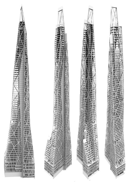
I need to make a random grids on series of towers that act as structure, like below. At the bottom of tower the grids are more dense and it becomes less as gets higher.
I wouldn't know where to start, any help or ready sample files available would be much appreciated.
Thanks
Views: 3930
Replies to This Discussion
-
Permalink Reply by peter fotiadis on
-
Hmm (I was absent from this noble Forum for quite a long period - blame CATIA)...
...you mean that you like to apply a Voronoi variable grid in a given brep ? (with "steel" alike rectangular/IPN/HEB/etc sections?). I'm thinking the very same problem (related with Carbon Fiber custom truss members and the likes).
The bad news are that random "things" (solidified "grids" via Exoskeleton) like these doesn't address your issue (or maybe they can?):
BTW: unfortunately the as above results are meshes (I hate meshes), thus useless for classic engineering purposes.
BTW: things marked with red are Grasshopper add-ons.
I'll try something with TSplines (4 Beta since the 3.4/3.4.1 builds they don't work) and I'll get back to you soon.
best, Peter
-
-
-
BTW: Although not a tower and although made with carbon fiber this case falls in a "similar" class of puzzle:
Create some 3d "grid"/structure (Pipe + TSplines) and then isolate the nodes in order to mastermind some kind of fabrication (via 3d printing). By isolate I mean send them to a decent MCAD (CATIA/NX) app and design the appropriate connecting metal parts (like a MERO space frame) etc etc etc...
...a task that requires nurbs and not meshes.
-
-
Permalink Reply by mrahmany on
-
Peter Thanks a lot for swift replies, much appreciated.
Although, not exactly what I was after they seem very helpful.
I am not particularly after curved shapes or smooth forms, but rather straight angles and edges, I think it may have something to do with using triangulation, I will play around see what I get out.
thanks
-
-
-
Well...was obvious that you are after I.M.Pei type of steel load bearing members (thus the liquid thing is utterly pointless - I've just included some samples to demonstrate the theoretical potential) .
But since we are engineers the issue here is not to create some abstract "straight" formation like this (and thicken it):
the issue is to handle that:
-
-
-
Good news:
Tried some "ideas" (all stupid) but nothing works with some elementary engineering way of thinking - for instance constraining the "skin" nodes with floor structural member axis blah blah.
Bad news:
Out of cigars and espresso
-
-
-
Above is what I was kinda after.
If you don't mind would you be able to send me over the GH file I will try play around with it a little to see if could get what I want.
I wish I was there to buy you some espresso..
BTW Thanks a lot for taking time to reply to my posts..
Much appreciated.
-
-
Permalink Reply by Homer Garcia Santana on
-
jitter/ramdom
-
-
-
Of course I will post here some(?) kind(??) of definition(???) as soon as is something ready(?) to make(???) something, he he.
PS: I wonder why any attempt to control some decent Delaunay triangulation fails miserably.
PS: Can weaverbird/paneling tools/evolute tools cut the mustard?
PS: Racha...this case is more complex than it appears (load bearing members instead of aluminum thin decorative "shade" type of stuff, BIG, severe angle connection restrictions per node, thermal bridges, dew point issues blah blah) - jitter/random was the very first "filter" to apply.
may the Force (the dark option) be with us
-
-
-
OK ... here's the most unfinished (and stupid) definition known to mankind.
1. When you "spread" points (and applying some, say, delauney algo on them) across the facades (spot the dihedral) ... well...hmm... points across the facade edges are not included (or may be some) and thus the whole thing is the art of pointless.
2. See the 1a unfinished part ... that defines internal boundaries for that purpose - then you need to create points across the edges, random reduce them and merging the list with the other points...blah blah.
3. That way each facade could yield structural members that touch the edges (where the biggest HEB/columns are expected to be). Obviously nodes are shared between facades with a common edge - the best logical approach for obvious real-life reasons.
4. The whole approach is stupid : here we need some Hoop snake "loop" control (that could take into account the critical connection angle constrain) in order to achieve a "progressive" deployment of the diagonal members in order to satisfy structural requirements and ... hmm...aesthetics. Free espresso for everyone is an added bonus.
5. Bottom to top design mentality is urgently required here: mastermind some 3d conceptual arrangement of nodes keeping in mind ... well...just 345,67 different real-life factors (but you could combine insulation and fireproofing if you use my favorite material: Foamglas - name with with one "s"). That way you can define the critical deployment planes : i.e. diagonal rigidity members, some facade aluminum system and floor main perimeter I-Beams MUST be in different planes.
I'll be back with a more stupid version of that thing.
may the Force ...blah blah
- Attachments:
-
-
 TheArtOfPointless-part1.gh, 64 KB
 -
TheArtOfPointless-part13dm.3dm, 125 KB
-
-
-
-
PS: These nodes are what happens when real-life takes over theory.
-
-
-
Nice nodes ( made in China suppose? Those guys can make everthing )
-
-
-
Talking about stupid solutions ( jajaja ...this is what I get out of the story).... but its a start for the kid
-
About
Welcome to
Grasshopper
Translate
Search
Photos
Videos
-
Ngon Mesh
Added by Parametric House 1 Comment 0 Likes
-
Minimal Surface
Added by Parametric House 1 Comment 0 Likes
© 2026 Created by Scott Davidson.
Powered by
![]()