algorithmic modeling for Rhino
Gridshell with similar length
Hello,
I need to get the knot-coordinates of the following problem:
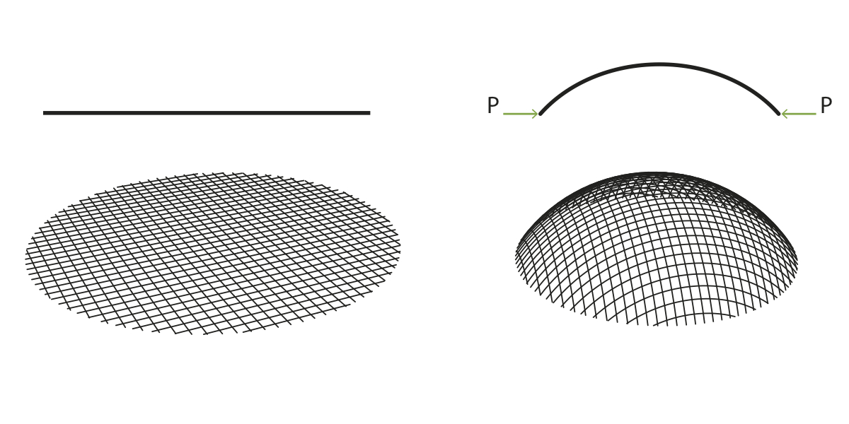
The surface is a half sphere and it has to become a gridshell with rhombus that have all the same length but not the same angle.
My master thesis is about the Multihalle Mannheim and there the wooden beams were connected on the ground and than pushed up and fixed in the gridshell.
Frei Otto had a compass method, with it he was able to find the coordinates of the knots. The picture shows the system.
I already read the posts about gridshells but this problem is not solved there...
I would be soooooo glad if someone could help me. I'm a beginner in grasshoppper and rhino and not able to get a glue how to solve the problem.
thanks a lot
Views: 4766
- Attachments:
-
-
 sphere method.jpg, 77 KB
-
Replies to This Discussion
-
Permalink Reply by Joseph Oster on
-
Hi,
I didn't understand most of your question or your attached diagram, but when I Googled "Multihalle Mannheim", I got interested - structures like this are fascinating.
So I started to re-create your diagram using a hemisphere with a single line - an intersection with the 'YZ' plane - divided, with small spheres at each division point (the green points in images below).
I took the intersections of the small spheres with the large hemisphere (the yellow circles below), made a shifted copy of that list and used 'Curve | Curve (CCX)' to find the points where they intersect (the blue points below).
Finally, I used an array of 'PFrames' instead of the single 'YZ' plane to cover the hemisphere.
Are the blue and green points useful to you? I'll be very interested to follow along with what you're doing.
- Attachments:
-
-
 gridshell_2015Jun27a.gh, 13 KB
-
-
-
-
This diagram from the article on Multihalle Mannheim makes it clear that my model is not correct. I should have read it first. Fascinating challenge.
-
-
-
And this must be too simple? Can this really be done on a half sphere? The dome shape in the diagram above looks only half as high - things fall apart the closer you get to the "equator" in this method.
- Attachments:
-
-
gridshell_2015Jun27b.gh, 13 KB
-
-
-
Permalink Reply by annika rensland on
-
Dear joseph,
thank you so much for your interest and help.
The first one looks very good. The second one has the problem that the lines near the ground are to long. Its not working in this almost vertical area.
I couldn't open the website you post. So I don't know why you think the first model is wrong. Could you tell me why you think its wrong?
I think its the correct way.
I found a master thesis about this subject. It's a really fascinating building. My thesis is about the structural engineering calculation and I need the knots for a finite elements calculation.
http://www.citg.tudelft.nl/over-faculteit/afdelingen/bouw-infra/sec...
http://homepage.tudelft.nl/p3r3s/MSc_projects/reportToussaint.pdf
-
-
-
ah well I see that the knots are sometimes only close to each other... the method of the thesis has two surfacelines in the beginning. And on this lines the spheres are oriented.
-
-
-
Good morning,
This page isn't loading for me either now: http://shells.princeton.edu/Mann1.html
I'll read the pages you posted and get back to you on this. It occurred to me later that the correct solution may be a combination of the two methods I used...
-
-
-
The .pdf is extremely comprehensive and very informative, thanks for that. A lot to absorb!
One of the first things that struck me, looking at the images (Figure 6.6: Creating sections), was that the two initial sections that define the starting point appear as curved lines in the top view - not what I expect from intersecting a surface with two planes?
So in the final result, the top view doesn't have a single straight line of points, though that is partly a result of the shape... a half peanut shell above, an ellipsoid below. Neither of my methods would achieve this.
Note that on page 118 (p. 132 of the PDF), it says:
With the grid generation tool it was found that bending curvatures become too large when the laths of the grid are bent to a (semi-)spherical surface. This problem was also found in the physical modelling process. [...] Large force was needed to pull the structure into a position, creating tension in parts of the structure (Figure 6.74). This effect can be compared with the tensioning of the fabric of a hyperbolic tent structure. Together with the results of the grid generation tool, this results show that it is hard to create a (semi-) spherical surface with a gridshell structure. It is therefore advisable to avoid such shapes when a gridshell structure is applied.
So the solution (obviously?) cannot depend on the nature of the surface; characteristics that apply only to one surface (a sphere) and not others.
Finally (for now), the code described in the PDF is RhinoScript, not Grasshopper, and I'm not confident that a solution is possible using GH alone. Iteration, recursion, stitching together the edges of the four quadrants - GH just isn't designed that way, and all appear to be necessary for this.
Not giving up but not confident either. There are some code guys here who would probably love this problem. Cheers.
-
-
Permalink Reply by Daniel Piker on
-
Hi Annika,
This is a topic that has come up numerous times on this forum, with lots of example definitions posted. I realize that digging through all the search results can take a while (I saw that there are nearly 800 hits for "gridshell") but many of the answers you seek are quite likely already in there.
Several full scale gridshell structures have been built using these definitions (both the Mannheim style starting from a flat grid and keeping the node-node distance fixed, and other non-developable gridshells).
Several examples of the former are described in this paper by Dragos Naicu, including one that was built in Romania in a project lead by him that I was also involved with. A version of the Grasshopper definition we used for the form-finding of that project is included in the examples folder with the Kangaroo 0.099 download.
In general this challenge of keeping edge lengths of a quad mesh equal while covering a curved surface will require iterative techniques (I think there are some analytical solutions for certain geometric primitives, but not for freeform shapes) and purely grasshopper solutions like the ones posted in this thread so far won't get you there without some additional scripting or plugins to allow this iteration.
The compass method you mention is usually referred to as a Chebyshev net, and I know Will Pearson has made a scripted implementation of this, and Arturo Tedeschi did a version with Hoopsnake (see here for both). I'm not sure either of those definitions have been posted though.
You can also use Kangaroo to generate these geometries in a number of ways. One way is to start with a flat grid, assign the members some bending stiffness and push it up into a 3-dimensional form, while keeping edge lengths fixed similar to how it would actually be erected. Another is to fix some points at the corners or boundaries and hang the mesh under gravity then invert it for a funicular geometry.
Another method (which is closer to the Chebyshev approach) for if you want to start from a pre-defined form, such as your sphere is to drape a flat mesh over the solid shape. I've attached here an updated example of doing this in Kangaroo2 (as I realize most of the older examples posted are using the previous version).
Gridshells are a fascinating topic. I hope this is all of some help.
- Attachments:
-
-
gridshell_drape.gh, 19 KB
-
-
-
-
Thank you so much for all your help Joseph and Daniel.
This is really amazing and you really made my day.
I just have two last questions:
- Is it correct how i tried to get the coordinates?
- How can I cut the mesh after the calculating (in the middle of the sphere) and get also the coordinates of these points?
thanks a thousand times!
-
-
-
i found it out by myself... i just baked the structure and than trimmed the lines in rhino.
^^
-
About
Welcome to
Grasshopper
Translate
Search
Photos
Videos
-
Inflate Mesh
Added by Parametric House 0 Comments 0 Likes
-
Voronoi Roof
Added by Parametric House 0 Comments 0 Likes
-
Tensile Column
Added by Parametric House 0 Comments 0 Likes
© 2025 Created by Scott Davidson.
Powered by
![]()