algorithmic modeling for Rhino
varying beam size/profile extrusions
Hi Jon,
Is there a "natural" way in geogym to make profile extrusions that vary in scale from one end to another?
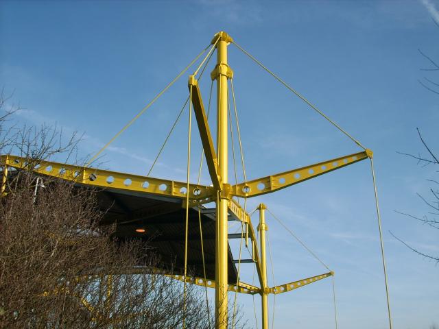
What I mean is something like the suspended members in the picture below. If you ignore the holes, what I am trying to achieve is the beam's depth/breadth size specificity. All I can think of is either lofting three different profile curves located at different points on a curve or orienting a profile and then scaling it throughout a curve. Is there a quicker way to do it with the plug-in?
Views: 1830
Replies to This Discussion
-
Permalink Reply by Jon Mirtschin on
-
Hi Rene,
Thanks for posting the question.
Yes, it's possible to define tapered members in IFC. I have enabled this to some extent. I've attached an example, the axis path must be on centreline (not a topmid cardinal point for the time being, I'll see if I can enable that). The revit addon will create a tapered family beam.
If it's not behaving as you need, let me know and I'll try to improve it ASAP.
Cheers,
Jon
- Attachments:
-

-
Permalink Reply by RENE on
-
Hi jon, I have this same question again but for a curve instead of a line. The ggIFCBSC component asks for an axis for the profile sweeping, but there is not tapering if it's a curve. I want the bottom part to be thicker...thanks in advance!
-
-
-
Take a look at the sectioned spine shape representation (that is similar to a rhino loft) and don't use a standard case component. If you can't get it to work and can send me the file I'll take a look.
-
-
Permalink Reply by Damon on
-
I know this is an old thread, but I found it trying to solve the problem of creating tapered beams using GG to import to Revit. Using your example above, this is the result I get:
As you can see, it isn't a tapered beam. It seems to be sweeping both profiles along the axis path.
Thoughts?
-
-
-
Hi Damon,
Thanks for the post. If I recall, soon after enabling the method in the example script, I found out there was an improved way of defining a tapered element in IFC4 (before that I was using a bit of a fudge). So looking at the old definition it seems I "broke" the previous way. I've attached a new sample that shows the newer method, is that acceptable?
Cheers,
Jon
- Attachments:
-
-
-
Jon,
As always, a super quick and helpful response! It works for what I need.
Thanks,
Damon
-
-
-
OK, so a little glitch, but I think I found a solution:
My custom profiles are drawn on the XY plane with their top midpoint at (0,0).
The axis lines in my Rhino model are top mid of the members.
If I set I=MID in the Beam Standard Case component, the GH preview looks good:
Unfortunately, when I bring that into Revit, it does this:
(The red centerline is a DWG import). When I edit the Structural Framing family, it is drawn with the top of the member at the reference plane.
So I can fix the problem if I select all the beams and set the "z Justification" parameter to "Top."
I tried drawing my profiles so that their center is at (0,0) and choosing I=TOPMID, but I get stranger behavior that I can't correct in Revit. Hope this is helpful information.
-
About
Welcome to
Grasshopper
Translate
Search
Photos
Videos
-
Ngon Mesh
Added by Parametric House 1 Comment 0 Likes
-
Minimal Surface
Added by Parametric House 0 Comments 0 Likes
-
Wind Pavilion
Added by Parametric House 0 Comments 0 Likes
© 2026 Created by Scott Davidson.
Powered by
![]()