algorithmic modeling for Rhino
Search Results - %E6%B5%B7%E5%8D%97%E4%B8%83%E6%98%9F%E5%BD%A9%E7%B2%A4%E6%B5%B7%E8%81%94%E5%86%9B%7Cwn4.com%7C%E8%BE%BD%E5%AE%81%E7%A6%8F%E5%BD%A912%E9%80%895%E4%BB%BB%E9%80%894%E6%8A%80%E5%B7%A7.w3b2s1.2023%E5%B9%B43%E6%9C%8819%E6%97%A56%E6%97%B68%E5%88%8624%E7%A7%92.ckrrkvuu4.cc
- Comment on: Topic 'Autodesk's world domination'
- Simpsons episode were Bart goes into a mall and in the time he goes in and out of a shop all others have been turned into Starbucks. I personally don't like it but you can't say they are crushing all competitors because, as far as i know, all owners of those software packages voluntarily sold their property for a good price. I would actually be more worried that an antitrust lawsuit was filed against Autodesk. For example, this is what happened with Rockefeller's Standard Oil: The antitrust case against Standard Oil also seems absurd because its share of the petroleum products market had actually dropped significantly over the years. From a high of 88 percent in 1890, Standard Oil's market share had fallen to 64 percent by 1911, the year in which the US Supreme Court reaffirmed the lower court finding that Standard Oil was guilty of monopolizing the petroleum products industry.[32] The court argued, in essence, that Standard Oil was a "large" company with many divisions, and if those divisions were in reality separate companies, there would be more competition. The court made no mention at all of the industry's economic performance; of supposed predatory pricing; of whether industry output had been restrained, as monopoly theory holds; or of any other economic factors relevant to determining harm to consumers. The mere fact that Standard Oil had organized some thirty separate divisions under one consolidated management structure (a trust) was sufficient reason to label it a monopoly and force the company to break up into a number of smaller units. To economists, "predatory pricing" is theoretical nonsense and has no empirical validity, either. In other words, the organizational structure that was responsible for the company's great efficiencies and decades-long price cutting and product improving was seriously damaged. Standard Oil became much less efficient as a result, to the benefit of its less efficient rivals and to the detriment of consumers. From: http://mises.org/daily/2317 (Beware, that site is very ideologically charged)…
- Added by Vicente Soler at 3:57pm on April 28, 2010
- Topic: Multiple Attractors Scaled by Independent Percentage Values
- points within the bounds of the site boundary and use each location as an attractor point controlling a variable at each point in the grid (radius of a circle/height of a cube/colour based on a gradient etc.).This would be based on proximity to the attractor points with the effect of each attractor point essentially scaled by the percentage associated with it. For example a location with 88% visitor rates would have a more dramatic effect than a location with 26% visitor rates. I've had a bit of a play around but can't seem to get beyond the point of what is shown in basic point attractor tutorials online. I'm definitely a novice. Here's how I figured it would be done: 1) Create a grid of source points within a boundary curve. 2) Select 18 pre-defined attractor points. 2) Measure the distance between the source points and the attractor points. 3) Invert this data so that variables increase with proximity rather than decrease. 4) Give each of the attractor points a strength value from 1-100% based on the visitor rates. 5) Use the scaled data to control a variable at each of the source points. 6) Create some way to control the drop-off rate of the effect from each point. It is at step 3 that I get completely lost. I hope my description is clear. Any help would be greatly appreciated, Adam …
- Added by Adam_M at 11:26pm on March 10, 2016
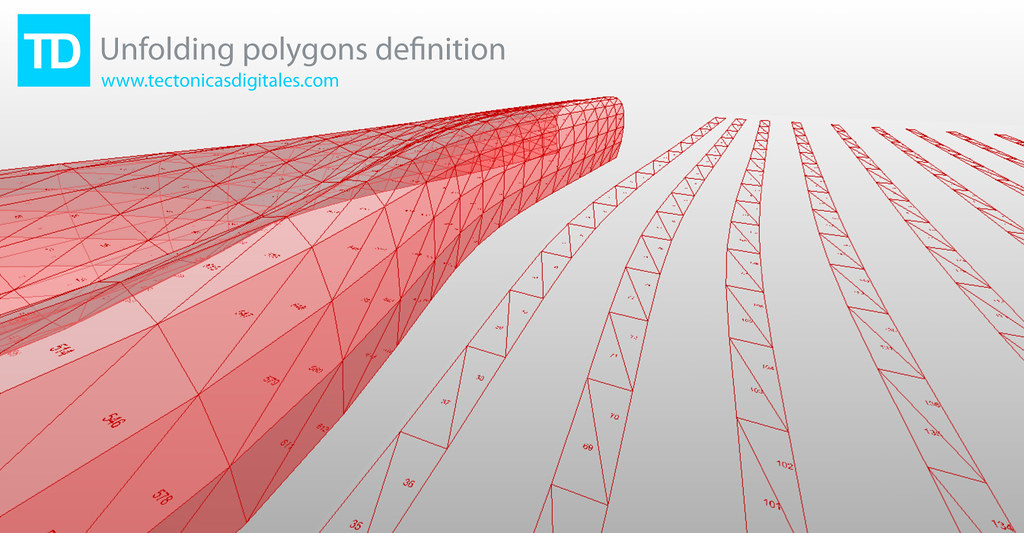
- Blog Post: Unfolding polygons definition
-
- Added by Francisco Calvo at 11:08am on February 8, 2010
- Topic: Smartgeometry 2012: Material Intensities - Workshop Applications close Jan 15th
- ers and researchers, programmers and artists, professionals and academics who come together for 4 days of intense collaboration, development, and design. The sg2012 Workshop will be organised around Clusters. Clusters are hubs of expertise. They comprise of people, knowledge, tools, materials and machines. The Clusters provide a focus for workshop participants working together within a common framework. Clusters provide a forum for the exchange of ideas, processes and techniques and act as a catalyst for design resolution. The Workshop is made up of ten Clusters that respond in diverse ways to the sg2012 Challenge Material Intensities. Applicants to the sg2012 Workshop will select their preferred cluster from the following: Beyond Mechanics Micro Synergetics Composite Territories Ceramics 2.0 Material Conflicts Transgranular Perspiration Reactive Acoustic Environments Form Follows Flow Bioresponsive Building Envelopes Gridshell Digital Tectonics More information about the Workshop and Clusters can be found here: http://smartgeometry.org/index.php?option=com_content&view=article&id=116&Itemid=131 The application process will close on January 15th, 2012. Full Fee $1500 Reduced Fee $750 Scholarship Fee $350 Fees include attendance to both the workshop and conference from March 19th-24th. Reduced Fee and Scholarships are available only for Academics, Students and Young Practitioners, and are awarded during a competitive peer review process. sg2012 takes place from 19-24 March 2012 at EMPAC (http://empac.rpi.edu/) and is hosted by Rensselaer Polytechnic Institute in Troy, upstate New York USA. The Workshop and Conference will be a gathering of the global community of innovators and pioneers in the fields of architecture, design and engineering. The event will be in two parts: a four day Workshop 19-22 March, and a public conference beginning with Talkshop 23 March, followed by a Symposium 24 March. The event follows the format of the highly successful preceding events sg2010 Barcelona and sg2011 Copenhagen. sg2012 Challenge Material Intensities Simulation, Energy, Environment Imagine the design space of architecture was no longer at the scale of rooms, walls and atria, but that of cells, grains and vapour droplets. Rather than the flow of people, services, or construction schedules, the focus becomes the flow of light, vapour, molecular vibrations and growth schedules: design from the inside out. The sg2012 challenge, Material Intensities, is intended to dissolve our notion of the built environment as inert constructions enclosing physically sealed spaces. Spaces and boundaries are abundant with vibration, fluctuating intensities, shifting gradients and flows. The materials that define them are in a continual state of becoming: a dance of energy and information. Material potential is defined by multiple properties: acoustical, chemical, electrical, environmental, magnetic, manufacturing, mechanical, optical, radiological, sensorial, and thermal. The challenge for sg2012 Material Intensities is to consider material economy when creating environments, micro-climates and contexts congenial for social interaction, activities and organisation. This challenge calls for design innovation and dialogue between disciplines and responsibilities. sg2010 Working Prototypes strove to emancipate digital design from the hard drive by moving from the virtual to the actual in wrestling with the tangible world of physical fabrication. sg2011 Building the Invisible focused on informing digital design with real world data. sg2012 Material Intensities strives to energise our digital prototypes and infuse them with material behaviour. They have the potential to become rich simulations informed by the material dynamics, chemical composition, energy flows, force fields and environmental conditions that feed back into the design process. More information can be found at http://www.smartgeometry.org Follow us on Twitter at http://twitter.com/smartgeometry…
- Added by Shane Burger at 12:29pm on December 13, 2011
- Comment on: Topic 'Heat Island Effect'
- umbrella of Urban Heat Island (UHI) and I am going to try to separate them out in order to give you a sense of the current capabilities in LB+HB. 1) UHI as defined as a recorded elevated air temperature in an urban area: If you have access to epw files for both an urban area and a rural area, you can use Ladybug to visualize and deeply explore the differences between the two weather files. Ladybug is primarily a tool for weather file visualization and analysis and it can be very helpful for understanding the consequences of UHI on strategies for buildings or on comfort. This said, if you do not have both rural and urban recorded weather data or you want to generate your own weather files based on criteria about urban areas (as it sounds like you want to do), this definition might not be so helpful. 2) UHI defined by air elevated air temperature but viewed as a computer model-able phenomenon resulting primarily from urban canyon geometry, building materials, and (to a lesser degree) anthropogenic heat: This definition seems to fit more with they type of thing that you are looking for but it is unfortunately very difficult and computationally intensive such that we do not currently have anything within Ladybug to do this right now. I can say that the state-of-the art for this type of modeling is an application called Town Energy Budget (TEB) and this is what all of the advanced UHI researches that I know use (http://www.cnrm.meteo.fr/surfex/spip.php?article7). Unfortunately for those trying to use it in professional practice, it can take a while to get comfortable with it and it currently runs exclusively on Linux (this does mean that it is open source, though, and that you can really get deep into the assumptions of the model). A couple years ago, a peer of mine translated almost all of TEB into Matlab language making it possible to run it on Windows if you have Matlab. He wrapped everything together into a tool called the Urban Weather Generator (UWG), which can take an epw file of a rural area and warp it to an urban area based on inputs that you give of building height, materials, vegetation, anthropogenic heat, etc. I would recommend looking into this for your project, although, bear in mind that is it not open source like the original TEB tool and that you may need to get a (very expensive) copy of MATLAB (http://urbanmicroclimate.scripts.mit.edu/uwg.php). 3) UHI as defined by a thermal satellite image of an urban area depicting an elevated average radiant environment that reaches a maximum a the city center and changes by land use: This is the definition of UHI that I am most familiar with and was the basis of much of my past research. I feel that it is also a definition of UHI that is a bit more in line with where a lot of contemporary UHI research is headed, which is away from the notion of UHI as a macro-scale meteorological phenomena that is averaged as an air temperature over a huge area towards one that accepts that different land uses have different microclimates and (importantly) different radiant environments. While the air temperature difference between urban and rural areas usually does not change more than 1-4 C, the radiant environment can be very different (on the order of 10-15 C differences). The best way to understand UHI in this context is with Thermal satellite images, for which there is ha huge database of publicly available data on NASA's glovis website (http://glovis.usgs.gov/) or their ECHO website (http://reverb.echo.nasa.gov/reverb/#utf8=%E2%9C%93&spatial_map=satellite&spatial_type=rectangle). I tend to use thermal data from LANDSAT 5-8 and ASTER satellites in my research. Unfortunately, there is a lot f bad data with a lot of cloud cover mixed in with the really good stuff and it can take some time to find good images. Also, there aren't too many programs that read the GeoTiff file format that you download the data as. I know that ArcGIS will read it, a program called ENVI will read it (I think that the open source QGIS can also red it). I have plans to write a set of components to bring this type of data into Rhino and GH (I may get to it a few months down the line). 4) UHI as a computer model-able notion of "Urban Microclimate" with consideration of local differences and the local radiant environment: This is where a lot of my research has lead and, thankfully, is an area that Honeybee can help you out a lot with. EnergyPlus simulations can output information on outside building surface temperatures and these can be very helpful in helping get a sense of the radiant environment around individual buildings. Right now, I am focusing just on using this data to fully model the indoor environments of buildings as you see in this video: https://www.youtube.com/watch?v=fNylb42FPIc&list=UUc6HWbF4UtdKdjbZ2tvwiCQ I have plans to move this methodology to the outdoors once I complete this initial application to the indoors. For now, you can use the "Surface result reader" and the "color surfaces based on EP result" components to get a sense of variation in the outside temperature of your buildings. I hope that this helped, -Chris …
- Added by Chris Mackey to Ladybug Tools at 3:54am on February 1, 2015
- Topic: Need help to optimize a space division
- oxes in the most efficient way within boundaries of object and follow the following constraints. The Goal: To fit 125 boxes in the most efficient way inside the total area. Starting Variables: (1) 40% of the Boxes need to be between 60 and 85MSQ. (2) 40% of the boxes need to be between 86 and 110MSQ. (3) 20% of the boxes need to be between 111 and 125mSQ. The breakdown doesn’t have to be exact to give the script some flexibility. Meaning you can have 41% +39% +20% = 100%. Constraints: 1. A total MAXIMUM area of approximately 1600M per layer. 2. A maximum of 8 layers for a total of 12,800M per layer. Optimization can make as little or as many as 8 layers vertical to accommodate all boxes. So if script can achieve with 3 levels great. If needed all 8 levels, that's fine too. However, pay attention to next constraint (#3). 3. Approximately 15% of that space on each layer is off limits. (internal area) (blue area in example script) and the shape of the boundary cannot be modified to accommodate box design resulting in jagged lines for the internal area. 4. All generated squares/rectangles must have at least 3m touching an outside border (The Green lines). 5. All boxes must also be touching minimum 1M of border of the blue line. 6. If the boxes generated go outside the green boundary, they must be fillet to maintain the straight lines of the green boundaries. 7. Get as many of the boxes as possible a view towards the dots. Could any one provide me a method or a way to start, if there are any useful links, please share with me. Thank you!…
- Added by Mohamed Elbangy to Space Syntax at 12:21pm on April 6, 2017
- Topic: Need help to optimize a space division
- Boxes in the most efficient way within boundaries of object and follow the following constraints. The Goal: To fit 125 boxes in the most efficient way inside the total area. Starting Variables: (1) 40% of the Boxes need to be between 60 and 85MSQ. (2) 40% of the boxes need to be between 86 and 110MSQ. (3) 20% of the boxes need to be between 111 and 125mSQ. The breakdown doesn’t have to be exact to give the script some flexibility. Meaning you can have 41% +39% +20% = 100%. Constraints: 1. A total MAXIMUM area of approximately 1600M per layer. 2. A maximum of 8 layers for a total of 12,800M per layer. Optimization can make as little or as many as 8 layers vertical to accommodate all boxes. So if script can achieve with 3 levels great. If needed all 8 levels, that's fine too. However, pay attention to next constraint (#3). 3. Approximately 15% of that space on each layer is off limits. (internal area) (blue area in example script) and the shape of the boundary cannot be modified to accommodate box design resulting in jagged lines for the internal area. 4. All generated squares/rectangles must have at least 3m touching an outside border (The Green lines). 5. All boxes must also be touching minimum 1M of border of the blue line. 6. If the boxes generated go outside the green boundary, they must be fillet to maintain the straight lines of the green boundaries. 7. Get as many of the boxes as possible a view towards the dots. Could any one provide me a method or a way to start, if there are any useful links, please share with me. Thank you! …
- Added by Mohamed Elbangy to Kangaroo at 12:22pm on April 6, 2017
- Topic: Need help to optimize a space division
- re is my problem... I need to arrange Boxes in the most efficient way within boundaries of object and follow the following constraints. The Goal: To fit 125 boxes in the most efficient way inside the total area. Starting Variables: (1) 40% of the Boxes need to be between 60 and 85MSQ. (2) 40% of the boxes need to be between 86 and 110MSQ. (3) 20% of the boxes need to be between 111 and 125mSQ. The breakdown doesn’t have to be exact to give the script some flexibility. Meaning you can have 41% +39% +20% = 100%. Constraints: 1. A total MAXIMUM area of approximately 1600M per layer. 2. A maximum of 8 layers for a total of 12,800M per layer. Optimization can make as little or as many as 8 layers vertical to accommodate all boxes. So if script can achieve with 3 levels great. If needed all 8 levels, that's fine too. However, pay attention to next constraint (#3). 3. Approximately 15% of that space on each layer is off limits. (internal area) (blue area in example script) and the shape of the boundary cannot be modified to accommodate box design resulting in jagged lines for the internal area. 4. All generated squares/rectangles must have at least 3m touching an outside border (The Green lines). 5. All boxes must also be touching minimum 1M of border of the blue line. 6. If the boxes generated go outside the green boundary, they must be fillet to maintain the straight lines of the green boundaries. 7. Get as many of the boxes as possible a view towards the dots. Could any one provide me a method or a way to start, if there are any useful links, please share with me. Thank you! …
- Added by Mohamed Elbangy to Octopus at 12:23pm on April 6, 2017
- Blog Post: Generative Performative Modeling via Grasshopper Ecotect through Geco
- Added by to] at 6:26am on July 16, 2010
- Topic: 3D printing survey
- greatly appreciate it!! You can write the number of the question and write your answer next to it, example: 1) a 2) c 3) a) Washington University in St. Louis 4) 2 weeks (1week+1week shipping) 5) 130 6) b 7) b The survey questions are as follows: 1) Did you 3D print before? 5) How much did it cost (in dollars)? a. Yes, for a school project a. Between 20 & 50 b. Yes, for a personal project b. Between 50 & 80 c. Between 80 & 120 2) Print size d. Please specify if otherwise: _____ dollars a. Between 2 & 6 cubic inches b. Between 6 & 12 cubic inches 6) Do you think the price was expensive? c. Between 12 & 20 cubic inches a. Not at all d. Please specify if otherwise: ____cubic inches b. A little bit expensive c. Very expensive 3) Where did you print your object? a. School 7) Were you satisfied with the printed object? b. Outside school: _________________ a. Yes, it was a great print without problems b. Not bad, some issues 4) How long did it take to print? c. I was not satisfied, very bad quality a. ___ days b. ___ weeks Thank you very much to all!! PS: If you did many 3D prints, you can post multiple answers. Wassef…
- Added by Wassef Dabboussi at 11:04am on April 13, 2013
About
Welcome to
Grasshopper
Translate
Search
Photos
Videos
-
Recrusive Split
Added by Parametric House 0 Comments 0 Likes
-
Table Field
Added by Parametric House 0 Comments 0 Likes
© 2024 Created by Scott Davidson.
Powered by
![]()