algorithmic modeling for Rhino
Search Results - %E6%9C%BA%E9%80%89%E6%8E%92%E5%88%97%E4%BA%94%E5%8F%B7%E7%A0%81%E6%9F%A5%E8%AF%A2%E7%BB%93%E6%9E%9C%7Cwn4.com%7C%E4%B8%83%E6%98%9F%E5%BD%A9%E5%AE%89%E7%84%B6%E6%B1%87.w3b2s1.2023%E5%B9%B43%E6%9C%8819%E6%97%A55%E6%97%B642%E5%88%864%E7%A7%92.ga5flkklk.com
- Event: Parametric design, Optimization and Fabrication Workshop
- ce attractors 3- Relation between mathematics and Form 4- Network surface and Paneling 5- Fabrication methods (slice3d, nesting, ...) 6- Structure and Architecture (Millipede) 7-Energy and form 8- Islamic patterns 9- Physics with kangaroo …
- Added by Parametric House at 11:18am on May 11, 2014
- Comment on: Topic 'Tropical Glare'
- ions are probably reflective of the prevailing humidity conditions (I just had a chat about this with my advisor, who incidentally also happens to be on the committee for LM-83). The Tregenza sky patches considered in daylighting calculations don't do a good job of incorporating the correct size of the sun into calculations. In the figure below, the sun on the right is the one considered for calculations in Daysim. You can get a more accurate answer by considering a more discretized sky, however, I am not aware if that is possible with Daysim (and therefore HB) right now. Therefore, your direct sun calculations are likely to be off somewhat depending on how much of it there is(I'd say overestimated). The calculations with humid sky, which are on account of the sky itself (and not the sun alone) are likely to be more relevant. Regarding your questions about studying weathering effects with LB/HB, I have no idea as that is something that I haven't looked into before. I am sure someone else on this list has a more informed opinion on this issue than I do. Your project, and your approach to it, seems really interesting and I am glad to be having this discussion :). Sarith …
- Added by Sarith Subramaniam to Ladybug Tools at 11:35am on September 2, 2016
- Comment on: Video 'Demonstrating the Heron Shapefile Importer'
- p; 3D Urban ModelingOn the topography subject I get the next message: "One or more boundaries may be outside the bounds of the topo dataset" I'm not sure if it's the .IMG file I'm loading since I found so many IMG files nearing my polyline area (Miami Lat:26 Lon:-81 aprox.) or maybe my polygon doesn't match the topo area? I have no idea why it isn't working :(On the Shapefile subject, haven't been able to find a Building Height SHP File, so far have downloaded around 8 SHP files which only contain Polylines, my solution is to meanwhile randomize Z heights, but of course this data is not "technically" correct.P.S.: I've already tried all example links and also the ones posted by you and Benjamin in this video.Been strugling last few days, hope you can help me, thanks in advance!!…
- Added by Diego Velázquez Camacho at 4:41pm on September 23, 2014
- Comment on: Topic 'Geco - UserProblems'
- try now to integrate Geco in an interdisciplinary architectural engineering studio: hoping we can show you some nice applications of your tool, I'll keep you update and sending now details by e-mail. Here the file (very welcome to be shared). It most probably contais trivial errors by me, thanks for helping and giving some tip! Gr. Michela FILE: Ok, right, I see the outputs update correctly. Origin of problems must be in some different mistake I do: - Incident radiation: I am not sure I understand what is going on: why I get so many 'not a number' ? (The Galapagos report is full of NaNs). Bio-Diversity: 0.887 Genome[0], Fitness=NaN, Genes [89% · 44%] { Record: Too many fitness values supplied } ... Genome[7], Fitness=NaN, Genes [74%] { Record: No fitness value was supplied } .... Genome[9], Fitness=NaN, Genes [37% · 11%] { Record: Genome was mutated to avoid collision Record: Too many fitness values supplied } - Daylight calculations: the geometry accumulates withouth deleting the previous models. As a consequance, results almost do not change after few varations (so, outputs get updated but do not vary). In current daylight definition: the first object being imported is the one where the grid has to fit; its setting makes it cancelling all the other objects during import. All the others, do not delete anything when imported. When running loops (manual or GA) that vary parameters, the entire geometry do not get cancelled - so I guess the loop does not pass back by the cancelling step, but imports only the geometry which has been varied by the parameters using the setting of that import component only? I will then try again by changing the order of the operations, but if you have specfic tips, let me know. THANKS! …
- Added by Michela Turrin to [uto] tools Plug-ins at 7:34am on December 18, 2010
- Blog Post: Unfolding polygons definition
-
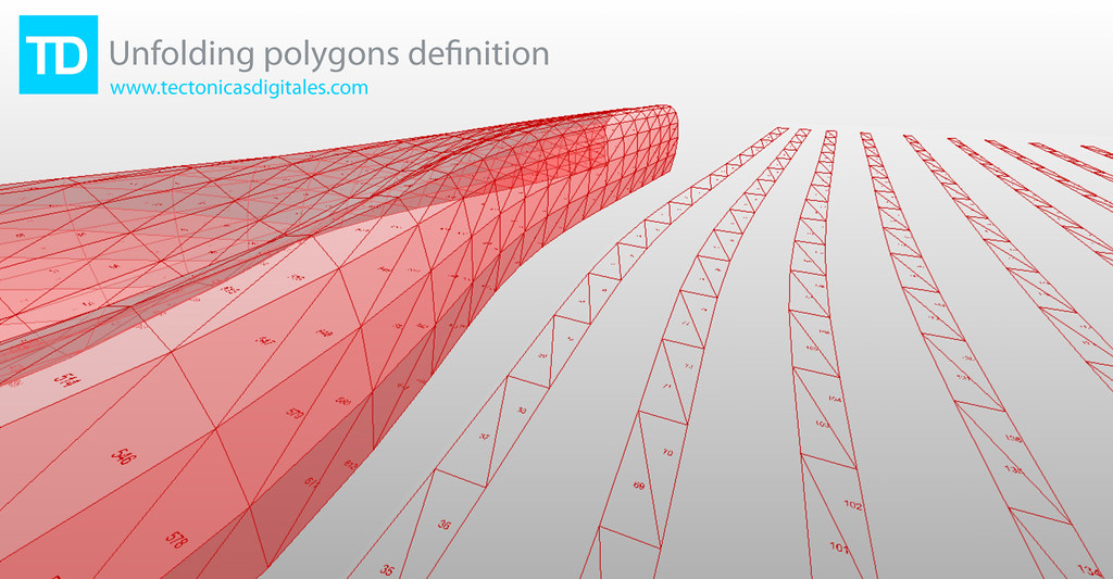
- Added by Francisco Calvo at 11:08am on February 8, 2010
- Topic: Couple of newbie questions about structuring & reusing 'programs'
- " (idiomatic) and easy way of doing things.So here come some basic questions: Is there a way to create custom components by grouping an existing sub-network together? I'm looking for a way to re-use parts of a program (something similar to subroutines), and to make the network look less cluttered. I found that it is possible to group components (ctrl-g), but this still displays them as separate blocks (too much clutter), and provides no way to re-use a sub-network in such a way that if it is modified in one place, all it's instances (all the places where it is re-used) also get modified. Is there a component that does nothing, just passes a signal through? Suppose I need to connect block A to blocks B1, B2, B3 (all three get the same input). Then I change my mind, and I decide to connect block C to these three, not A. In this case it will be necessary to change three connections, not just one. I'm looking for an easy way to do this by a single rewiring, not three. (This came up in a practical situation). Finally, a related question: is there a component that acts as a switch, so I can choose which signal it passes through out of a possible set of choices? For example, suppose that a set of objects can be coloured based on a number of different properties (size, positions, rotation, etc.) I'm looking for a way to switch between these very easily, without the need to do much rewiring. Thank you in advance for any replies / useful comments, even general ones on how to easily structure a large Grasshopper program/network.…
- Added by Szabolcs at 5:47am on July 9, 2010
- Topic: Sky Factor (Rights to Light) BRE
- at 0.85m above the floor. I copy paste from the Appendix E:Rights to Light of the book "Paul Littlefair, Site Layout Planning for Daylight and Sunlight, A good practice, BRE Press, p.60" which is the primary guide for evaluating the impact of new construction to the Rights to Light of the existing adjustment buildings: "The accepted way of calculating the loss of light is to compute the sky factor at a series of points on the working plane. In dwellings, the working plane height is usually taken to be 0.85 m (two feet nine inches). The sky factor is the ratio of the illuminance directly received from a uniform sky at the point indoors, to the illuminance outdoors under an unobstructed hemisphere of this sky. No allowance is made for glass losses or light blocked by glazed bars and (usually) window frames; nor is reflected light included, either from interior surfaces or obstructions outside. Thus the sky factor is not the same as the CIE daylight factor (see Appendix C). The sky factor is often calculated using a Waldram diagram, but this is a different Waldram diagram to Figure B1 in Appendix B, which should not be used for this purpose." Thought couldn't find the specific Waldram diagram for this case from the references, I assume contemporary analytical tools should exist to calculate it. I used your Vertical Sky Component process and culled the mesh faces lower than 0.2% but I believe because of they type of the radiance analysis as you have explained it before (stochastic method) it doesn't create one continuous edge, as you can see in the attached image. Thanks, Dimitris…
- Added by Dimitrios Papadopoulos to Ladybug Tools at 2:49pm on August 25, 2014
- Comment on: Topic 'How is this stuff done,..??? any idea,.?'
- button to generate such complicated and unruled geometry. Seriously, if you don't understand a geometry, how can you solve the structural needs and the bloody fabrication. Giant fast prototyping machines doesn't exist! In a era where ressources and energy is getting scarce, I don't understand this trend of fancy no sence look like organic buildings. They just look organic in our human perception. Nature builds things with define physical and biochemicals rules, and this is why when they grow, they look like that. You should study Frei Otto publication from the 80's.. the IL publications. They were using physical models to generate physical structures that would be build in the physical world. Computers and softwares are dangerous as we distach from reality. We put all this effort to generate these fancy forms, but no brain is put in structural optimization, energy efficiency (for instance in relation with the sun, or other natural elements) IT technology goes faster than the time we have to reflect about it. (not talking about the technics). As Frei Otto told me personally in our last discussion (talking about philosophy and architecture): " We have to define the OPEN QUESTIONS. Once these questions will be defined, you'll get answers". I think we are getting to a question here: " How to use this technology to solve problems in Architecture?" Before that " What are the real problems in architecture?" Maybe David should make a component for that? For instance, a button that could solve the loging and infrastructure problems for these millions of people living in the slums of Mumbai... What about that Krish Raj?…
- Added by SamuElf at 1:48am on September 18, 2009
- Comment on: Topic 'Tell us all about it...'
- igner called Christophe Barreau. http://www.christophe-barreau.fr/ We design sail catamarans from 40' to 80' and occasionally some other stuff. One may know it's a quite uncertain activity so I find myself tacking upwind on other seas from time to time, such as product design and jewelry. I also have side projects with mates regarding hi-fi or RC planes. As for "static" architecture I had a couple experiences working on large "complex" buildings. Sadly French architects are not very familiar with BIM, parametric or even precise 3d modeling so I've been hired to introduce GH in the workflow. I'm an un-authorized rhino trainer, sorry to say, but I just love teaching and meeting new faces, although I'm not as devoted as Danny ;) I've been using GH both for modeling and analysis for about three years now and I'll daresay I became pretty good at it... I'm not a geek at all but it's just so useful, and it's really worth it sometimes €€€!…
- Added by Fred Becquelin to The Union of Naval Architects at 10:35am on July 11, 2012
- Comment on: Topic 'Self Shading perforated dia-grid screen.'
- ke 20 samples per day, 50 days out of the year for 1000 samples) from each panel and calculate the % of occlusion. Allow that % to be the % "open" of each panel. Design the opening in each panel to be something cool and proportional. Profit. You could even break it down by a finite number of available panel types(say 0%, 20%, 40%, 60%, 80% open) and create an efficient production. All of these things can be paramterized to allow for more samples or more panel types as needed or based on your calculation limits. The only exception would be proper environmental analysis, say, if you were trying to reduce solar gain in summer and allow for it in winter. You would want to split this calculation between when you need to be gaining heat and where you want to be shading. Then extrapolate the percentage between the two. You may even need a gradient of heat gain through fall/spring. The possibilities depend on how much you know about the mechanical requirements of the area/building. That would be my approach. If I have more time tonight I will try and put something together on this as its been something I'd like to have in my back pocket.... Edit: You would also need to analyze the angle of incidence as it could have an effect on the amount of solar gain.....…
- Added by Phil Kolbo at 1:17pm on March 12, 2013
About
Welcome to
Grasshopper
Translate
Search
Photos
Videos
-
Parameric Roof
Added by Parametric House 0 Comments 0 Likes
-
Recrusive Split
Added by Parametric House 0 Comments 0 Likes
-
Table Field
Added by Parametric House 0 Comments 0 Likes
© 2024 Created by Scott Davidson.
Powered by
![]()