algorithmic modeling for Rhino
Search Results - %E7%94%98%E8%82%83%E5%BF%AB3%E5%B9%B3%E5%8F%B0%7Cwn4.com%7C%E6%A1%83%E8%8A%B1%E5%B2%9B%E5%BD%A9%E7%A5%A8%E5%B9%B3%E5%8F%B0%E7%99%BB%E9%99%86.w3b2s1.2023%E5%B9%B43%E6%9C%8819%E6%97%A57%E6%97%B640%E5%88%862%E7%A7%92.4i6e6g6eg
- Topic: Grasshopper error message on start
- - Exception occured during processing of command: Grasshopper Plug-In = Grasshopper Font 'Segoe UI' does not support style 'Regular'. Stack trace: at System.Drawing.Font.CreateNativeFont() at System.Drawing.Font.Initialize(FontFamily family, Single emSize, FontStyle style, GraphicsUnit unit, Byte gdiCharSet, Boolean gdiVerticalFont) at System.Drawing.Font.Initialize(String familyName, Single emSize, FontStyle style, GraphicsUnit unit, Byte gdiCharSet, Boolean gdiVerticalFont) at System.Drawing.Font..ctor(String familyName, Single emSize, FontStyle style, GraphicsUnit unit, Byte gdiCharSet) at Grasshopper.GUI.GH_DocumentEditor.InitializeComponent() in C:\dev\Grasshopper\1.0\root\src\GH_DocumentEditor.Designer.vb:line 329 at Grasshopper.GUI.GH_DocumentEditor..ctor() in C:\dev\Grasshopper\1.0\root\src\GH_DocumentEditor.vb:line 1779 at Grasshopper.Plugin.Commands.ShowGrasshopperEditor(Boolean ShowUponLoad) in C:\dev\Grasshopper\1.0\root\src\GH_GrasshopperCommands.vb:line 22 at Grasshopper.Plugin.Commands.Run_Grasshopper() in C:\dev\Grasshopper\1.0\root\src\GH_GrasshopperCommands.vb:line 94 at GrasshopperPlugin.GrasshopperCommand.RunCommand(IRhinoCommandContext context) at RhDN_TemplateCommand<CRhinoCommand,RMA::Rhino::MRhinoCommand>.RunCommand(RhDN_TemplateCommand<CRhinoCommand\,RMA::Rhino::MRhinoCommand>* , CRhinoCommandContext* context) --------------------------- OK --------------------------- I am using grasshopper 0.8.0050 and Rhino 4 SR8. I tried uninstalling it, and then installing it again. The same. It is interesting that until yesterday, everything was fine. What could possibly be the cause of a problem? Thank you.…
- Added by djordje at 3:07am on June 29, 2012
- Event: Parametric design, Optimization and Fabrication Workshop
- ce attractors 3- Relation between mathematics and Form 4- Network surface and Paneling 5- Fabrication methods (slice3d, nesting, ...) 6- Structure and Architecture (Millipede) 7-Energy and form 8- Islamic patterns 9- Physics with kangaroo …
- Added by Parametric House at 11:18am on May 11, 2014
- Comment on: Topic 'Autodesk's world domination'
- Simpsons episode were Bart goes into a mall and in the time he goes in and out of a shop all others have been turned into Starbucks. I personally don't like it but you can't say they are crushing all competitors because, as far as i know, all owners of those software packages voluntarily sold their property for a good price. I would actually be more worried that an antitrust lawsuit was filed against Autodesk. For example, this is what happened with Rockefeller's Standard Oil: The antitrust case against Standard Oil also seems absurd because its share of the petroleum products market had actually dropped significantly over the years. From a high of 88 percent in 1890, Standard Oil's market share had fallen to 64 percent by 1911, the year in which the US Supreme Court reaffirmed the lower court finding that Standard Oil was guilty of monopolizing the petroleum products industry.[32] The court argued, in essence, that Standard Oil was a "large" company with many divisions, and if those divisions were in reality separate companies, there would be more competition. The court made no mention at all of the industry's economic performance; of supposed predatory pricing; of whether industry output had been restrained, as monopoly theory holds; or of any other economic factors relevant to determining harm to consumers. The mere fact that Standard Oil had organized some thirty separate divisions under one consolidated management structure (a trust) was sufficient reason to label it a monopoly and force the company to break up into a number of smaller units. To economists, "predatory pricing" is theoretical nonsense and has no empirical validity, either. In other words, the organizational structure that was responsible for the company's great efficiencies and decades-long price cutting and product improving was seriously damaged. Standard Oil became much less efficient as a result, to the benefit of its less efficient rivals and to the detriment of consumers. From: http://mises.org/daily/2317 (Beware, that site is very ideologically charged)…
- Added by Vicente Soler at 3:57pm on April 28, 2010
- Topic: Multiple Attractors Scaled by Independent Percentage Values
- points within the bounds of the site boundary and use each location as an attractor point controlling a variable at each point in the grid (radius of a circle/height of a cube/colour based on a gradient etc.).This would be based on proximity to the attractor points with the effect of each attractor point essentially scaled by the percentage associated with it. For example a location with 88% visitor rates would have a more dramatic effect than a location with 26% visitor rates. I've had a bit of a play around but can't seem to get beyond the point of what is shown in basic point attractor tutorials online. I'm definitely a novice. Here's how I figured it would be done: 1) Create a grid of source points within a boundary curve. 2) Select 18 pre-defined attractor points. 2) Measure the distance between the source points and the attractor points. 3) Invert this data so that variables increase with proximity rather than decrease. 4) Give each of the attractor points a strength value from 1-100% based on the visitor rates. 5) Use the scaled data to control a variable at each of the source points. 6) Create some way to control the drop-off rate of the effect from each point. It is at step 3 that I get completely lost. I hope my description is clear. Any help would be greatly appreciated, Adam …
- Added by Adam_M at 11:26pm on March 10, 2016
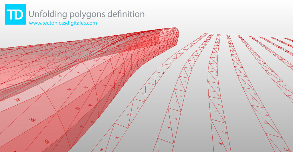
- Blog Post: Unfolding polygons definition
-
- Added by Francisco Calvo at 11:08am on February 8, 2010
- Topic: Sky Factor (Rights to Light) BRE
- at 0.85m above the floor. I copy paste from the Appendix E:Rights to Light of the book "Paul Littlefair, Site Layout Planning for Daylight and Sunlight, A good practice, BRE Press, p.60" which is the primary guide for evaluating the impact of new construction to the Rights to Light of the existing adjustment buildings: "The accepted way of calculating the loss of light is to compute the sky factor at a series of points on the working plane. In dwellings, the working plane height is usually taken to be 0.85 m (two feet nine inches). The sky factor is the ratio of the illuminance directly received from a uniform sky at the point indoors, to the illuminance outdoors under an unobstructed hemisphere of this sky. No allowance is made for glass losses or light blocked by glazed bars and (usually) window frames; nor is reflected light included, either from interior surfaces or obstructions outside. Thus the sky factor is not the same as the CIE daylight factor (see Appendix C). The sky factor is often calculated using a Waldram diagram, but this is a different Waldram diagram to Figure B1 in Appendix B, which should not be used for this purpose." Thought couldn't find the specific Waldram diagram for this case from the references, I assume contemporary analytical tools should exist to calculate it. I used your Vertical Sky Component process and culled the mesh faces lower than 0.2% but I believe because of they type of the radiance analysis as you have explained it before (stochastic method) it doesn't create one continuous edge, as you can see in the attached image. Thanks, Dimitris…
- Added by Dimitrios Papadopoulos to Ladybug Tools at 2:49pm on August 25, 2014
- Topic: Excel 2010 InteropServices fail
- ice 2007. So I went out and bought Office 2010, and all my Excel interopservices vb.net scripts are now failing. They had all worked fine before...now when I execute they give the following error: error: Invalid class string (Exception from HRESULT: 0x800401F3 (CO_E_CLASSSTRING)) (line: 0) Here's the boiled down script: If activate = True Then Dim oldCI As System.Globalization.CultureInfo = system.Threading.Thread.CurrentThread.CurrentCulture System.Threading.Thread.CurrentThread.CurrentCulture = New System.Globalization.CultureInfo("en-US") Dim xlApp As Object xlApp = System.Runtime.InteropServices.Marshal.GetActiveObject("Excel.Application") Dim xlSheet As Object xlSheet = xlApp.ActiveSheet xlSheet.Range("A1").Value = "test" End If The failure happens with the addition of the InteropServices line. I'm mid-project right now, and it's pretty critical that I regain the ability to go back and forth from GH to Excel in the scripting environment...does anyone know if I need to deactivate any security options in Windows, make sure any dll's are properly installed...anything? I've tried all of the other Excel components that various users here have already been generous enough to share (my scripts are all based on them). I can't seem to find any documentation (that I understand) about this particular error message, or how to fix it. Really could use a little help! thanks in advance, Dave…
- Added by David Stasiuk at 2:20am on January 24, 2011
- Topic: Radiance: Concave buildings beam convergence effect
- is post on the same subject: http://www.radiance-online.org/pipermail/radiance-general/2008-March/004856.html But I don't understand exactly how to assign the materials to the surface. When I use the Honeybee_CreateHBSrfs component it gives me an error: 1. Solution exception:Faild to import void glass glass_alt_mat003 0.96 0.96 0.96 void brightfunc glass_angular_effect2 A1+(1-A1)*(exp(-5.85*Rdot)-0.00287989916) .01 0.08 glass_angular_effect mirror glass_mat1 glass_alt_mat03 1 1 1 Have you ever solved the same issue? If possible, how would you simulate this effect with Honeybee? Any help would be appreciated…
- Added by Aymeric to Ladybug Tools at 3:16am on February 23, 2017
- Comment on: Topic 'Heat Island Effect'
- umbrella of Urban Heat Island (UHI) and I am going to try to separate them out in order to give you a sense of the current capabilities in LB+HB. 1) UHI as defined as a recorded elevated air temperature in an urban area: If you have access to epw files for both an urban area and a rural area, you can use Ladybug to visualize and deeply explore the differences between the two weather files. Ladybug is primarily a tool for weather file visualization and analysis and it can be very helpful for understanding the consequences of UHI on strategies for buildings or on comfort. This said, if you do not have both rural and urban recorded weather data or you want to generate your own weather files based on criteria about urban areas (as it sounds like you want to do), this definition might not be so helpful. 2) UHI defined by air elevated air temperature but viewed as a computer model-able phenomenon resulting primarily from urban canyon geometry, building materials, and (to a lesser degree) anthropogenic heat: This definition seems to fit more with they type of thing that you are looking for but it is unfortunately very difficult and computationally intensive such that we do not currently have anything within Ladybug to do this right now. I can say that the state-of-the art for this type of modeling is an application called Town Energy Budget (TEB) and this is what all of the advanced UHI researches that I know use (http://www.cnrm.meteo.fr/surfex/spip.php?article7). Unfortunately for those trying to use it in professional practice, it can take a while to get comfortable with it and it currently runs exclusively on Linux (this does mean that it is open source, though, and that you can really get deep into the assumptions of the model). A couple years ago, a peer of mine translated almost all of TEB into Matlab language making it possible to run it on Windows if you have Matlab. He wrapped everything together into a tool called the Urban Weather Generator (UWG), which can take an epw file of a rural area and warp it to an urban area based on inputs that you give of building height, materials, vegetation, anthropogenic heat, etc. I would recommend looking into this for your project, although, bear in mind that is it not open source like the original TEB tool and that you may need to get a (very expensive) copy of MATLAB (http://urbanmicroclimate.scripts.mit.edu/uwg.php). 3) UHI as defined by a thermal satellite image of an urban area depicting an elevated average radiant environment that reaches a maximum a the city center and changes by land use: This is the definition of UHI that I am most familiar with and was the basis of much of my past research. I feel that it is also a definition of UHI that is a bit more in line with where a lot of contemporary UHI research is headed, which is away from the notion of UHI as a macro-scale meteorological phenomena that is averaged as an air temperature over a huge area towards one that accepts that different land uses have different microclimates and (importantly) different radiant environments. While the air temperature difference between urban and rural areas usually does not change more than 1-4 C, the radiant environment can be very different (on the order of 10-15 C differences). The best way to understand UHI in this context is with Thermal satellite images, for which there is ha huge database of publicly available data on NASA's glovis website (http://glovis.usgs.gov/) or their ECHO website (http://reverb.echo.nasa.gov/reverb/#utf8=%E2%9C%93&spatial_map=satellite&spatial_type=rectangle). I tend to use thermal data from LANDSAT 5-8 and ASTER satellites in my research. Unfortunately, there is a lot f bad data with a lot of cloud cover mixed in with the really good stuff and it can take some time to find good images. Also, there aren't too many programs that read the GeoTiff file format that you download the data as. I know that ArcGIS will read it, a program called ENVI will read it (I think that the open source QGIS can also red it). I have plans to write a set of components to bring this type of data into Rhino and GH (I may get to it a few months down the line). 4) UHI as a computer model-able notion of "Urban Microclimate" with consideration of local differences and the local radiant environment: This is where a lot of my research has lead and, thankfully, is an area that Honeybee can help you out a lot with. EnergyPlus simulations can output information on outside building surface temperatures and these can be very helpful in helping get a sense of the radiant environment around individual buildings. Right now, I am focusing just on using this data to fully model the indoor environments of buildings as you see in this video: https://www.youtube.com/watch?v=fNylb42FPIc&list=UUc6HWbF4UtdKdjbZ2tvwiCQ I have plans to move this methodology to the outdoors once I complete this initial application to the indoors. For now, you can use the "Surface result reader" and the "color surfaces based on EP result" components to get a sense of variation in the outside temperature of your buildings. I hope that this helped, -Chris …
- Added by Chris Mackey to Ladybug Tools at 3:54am on February 1, 2015
- Blog Post: Generative Performative Modeling via Grasshopper Ecotect through Geco
- Added by to] at 6:26am on July 16, 2010
About
Welcome to
Grasshopper
Translate
Search
Photos
Videos
© 2024 Created by Scott Davidson.
Powered by
![]()