algorithmic modeling for Rhino
Search Results - %E5%8D%97%E6%96%B9%E5%8F%8C%E8%89%B2%E7%90%8317152%E6%9C%9F%E9%A2%84%E6%B5%8B%E3%80%8E8TBH%C2%B7COM%E3%80%8F%E8%80%81%E9%94%A316122%E6%9C%9F%E5%8F%8C%E8%89%B2%E7%90%83%E5%BC%80%E5%A5%96%E7%BB%93%E6%9E%9C2023%E5%B9%B43%E6%9C%8819%E6%97%A513%E6%97%B629%E5%88%8647%E7%A7%92.H5c2a3.z5ljbbjhh
- Comment on: Topic 'Radiant Asymmetry and MRT'
- on this, but to my understanding, the Δt_pr used is the same - the equations used to calculate are not. Take a look at this (from EN 7730 as well): If I can make some wishes too; it would be cool, if you included the last local comfort metrics from EN7730 in LB/HB as well. Besides the local asymmetry there are: an equation for warm/cold floors, stratification and draught. I know, that you will need preform a CFD simulation to properly calculate stratification and draught, but the comfort equations are really simple and seeing that you have(might have) a CFD tool under way it could be useful. Anyways I think it would possible to import external generated CFD data to grasshopper. The pictures in my previous post are from a paper called: "A simplified calculation method for checking the indoor thermal climate" by B.W. Olesen, it can be found in ASHRAE 1983, vol. 25, issue 5. I don't know if there have been any updates to it since '83. Looking forward for the new components, and if there is anything I can help with please let me know. /Christian …
- Added by Christian Kongsgaard to Ladybug Tools at 12:47pm on April 6, 2016
- Topic: Arcs for only convex 'inner' corners and orieneted correctly.. HELP!!! fabrication process
- te some cut sheets, but not to optmize material, rather define some cut lines. Everything that I am cutting is made of planar wood elements, but there are very specific geometries (mostly straight lines) and I have to put tolerances and radiasas at the corners in order to cut on the cnc mill. Spending time to figure out how to automate is necessary, but I am stuck! One thing the definition is doing is taking my brep modeled components in rhino and makking them into 2d close curves and laying them side by side. It works...not ideal as its not layed out in a sheet, but that is not the most important part. Another particular problem is that you will see some notches in the curves, which other pieces will slip into, so different slots need different specific offsets (making them larger) as a toelrance to allow for material play. This I don't even know how to set up so maybe it will just have to wait. THE MAIN QUESTION, and super important would be, LIFESAVER: At all 'inward' corners...which I think will always mean concave corners (most are 90 degrees, but are within to sides, instead of a corner sticking out). I'm sure its obviousy, but the reason being the outward corners a circular dril bit can cut, but inward ones need an arc profile extended beyond where the corner of the other piece will fit into. The drill bit i am using is 6mm, so 6mm diamters arcs is what i'm working with. I have managed to put such an arc at every vertices of each cut piece. The problem being some stick outward isntead of cutting into the piece. So each one needs to be orieneted correctly. Ideally they would also only draw into inward corners, but I can always delete them out. I think maybe I am missing a more logical mathematical way of defining? For these geometries it is not very important which side the half circle arc in on in the inward corners, but I also have some geometries that I will have to control where the circles face according to the rest of the cut piece. The cutouts in the middle of the pieces that are curves do not need such corners obviously. The picture is an example drawn I hope this isn't too specific and long. in general though automating fabrication, and controling pracitcal math and orientation problems like this is itnersting to me! THANKS…
- Added by Elliot Mistur at 12:55pm on July 20, 2011
- Event: Grasshopper Training at McNeel Europe
- derstanding of the graphical algorithm editor, and then dive into more complex parametric models. We’ll also learn tricks to keep our project responsive and enjoyable to use.Course outline covering similar content as the first part of the primer(http://www.grasshopper3d.com/page/tutorials-1) novel material duration: 3 days (24 hours) Including An understanding of the Grasshopper interface and the visual programming theory Base parameters, large numbers of points and vectors, and small geometrical instances Data flow Troubleshooting definition problems and solutions Know the main component types Be able to join, and manage connections and trees Expressions for both calculation and boolean creation Understand Data Matching and casting Managing long lists of objects within Grasshopper Have an understanding of the functioning of Grasshopper components Experience creating definitions Parametric geometry examples, like attractors and list culling Re-utilizable modeling examples: colored panelization, surface population, gradient and picture sampling and manipulation, catenary line and weaving Spline animation examples Getting ready to prepare own definitions in groups More information... …
- Added by Giulio Piacentino at 4:54am on January 10, 2011
- Topic: Grasshopper error message on start
- - Exception occured during processing of command: Grasshopper Plug-In = Grasshopper Font 'Segoe UI' does not support style 'Regular'. Stack trace: at System.Drawing.Font.CreateNativeFont() at System.Drawing.Font.Initialize(FontFamily family, Single emSize, FontStyle style, GraphicsUnit unit, Byte gdiCharSet, Boolean gdiVerticalFont) at System.Drawing.Font.Initialize(String familyName, Single emSize, FontStyle style, GraphicsUnit unit, Byte gdiCharSet, Boolean gdiVerticalFont) at System.Drawing.Font..ctor(String familyName, Single emSize, FontStyle style, GraphicsUnit unit, Byte gdiCharSet) at Grasshopper.GUI.GH_DocumentEditor.InitializeComponent() in C:\dev\Grasshopper\1.0\root\src\GH_DocumentEditor.Designer.vb:line 329 at Grasshopper.GUI.GH_DocumentEditor..ctor() in C:\dev\Grasshopper\1.0\root\src\GH_DocumentEditor.vb:line 1779 at Grasshopper.Plugin.Commands.ShowGrasshopperEditor(Boolean ShowUponLoad) in C:\dev\Grasshopper\1.0\root\src\GH_GrasshopperCommands.vb:line 22 at Grasshopper.Plugin.Commands.Run_Grasshopper() in C:\dev\Grasshopper\1.0\root\src\GH_GrasshopperCommands.vb:line 94 at GrasshopperPlugin.GrasshopperCommand.RunCommand(IRhinoCommandContext context) at RhDN_TemplateCommand<CRhinoCommand,RMA::Rhino::MRhinoCommand>.RunCommand(RhDN_TemplateCommand<CRhinoCommand\,RMA::Rhino::MRhinoCommand>* , CRhinoCommandContext* context) --------------------------- OK --------------------------- I am using grasshopper 0.8.0050 and Rhino 4 SR8. I tried uninstalling it, and then installing it again. The same. It is interesting that until yesterday, everything was fine. What could possibly be the cause of a problem? Thank you.…
- Added by djordje at 3:07am on June 29, 2012
- Comment on: Topic 'Python: longer version of Rhino.Geometry.CreatePatch expected IEnumerable[Geome…'
- see in my bottom post image there is only one isocurve showing in U and V. In Grasshopper there's no surface rebuild? Well, the same old Grasshopper Patch command will let you specify spans I guess, to make a surface from a planar curve, but it won't work for things with holes since they will just fill in! You can recreate a surface painfully by untrimming, adding many UV points, rebuilding from those points, then retrimming with the original surface info, but the retrimming simply fails. If you make a planar surface from a curve in Rhino, you end up with utterly no point editability: No wonder my CreatePatch tests were a failure. The starting surface could not be distorted except in the extreme case of moving four corner points! I have no idea how to successfully rebuild a surface akin to the Rhino rebuild command. It's great to be able to prototype in Grasshopper, but with Python I can rebuild easily ( http://4.rhino3d.com/5/rhinocommon/?topic=html/M_Rhino_Geometry_Surface_Rebuild.htm ;), so I guess I should start a collection, like peter, of little script components for prototyping with.…
- Added by Nik Willmore at 6:18am on February 26, 2016
- Comment on: Video 'Demonstrating the Heron Shapefile Importer'
- p; 3D Urban ModelingOn the topography subject I get the next message: "One or more boundaries may be outside the bounds of the topo dataset" I'm not sure if it's the .IMG file I'm loading since I found so many IMG files nearing my polyline area (Miami Lat:26 Lon:-81 aprox.) or maybe my polygon doesn't match the topo area? I have no idea why it isn't working :(On the Shapefile subject, haven't been able to find a Building Height SHP File, so far have downloaded around 8 SHP files which only contain Polylines, my solution is to meanwhile randomize Z heights, but of course this data is not "technically" correct.P.S.: I've already tried all example links and also the ones posted by you and Benjamin in this video.Been strugling last few days, hope you can help me, thanks in advance!!…
- Added by Diego Velázquez Camacho at 4:41pm on September 23, 2014
- Comment on: Topic 'Geco - UserProblems'
- try now to integrate Geco in an interdisciplinary architectural engineering studio: hoping we can show you some nice applications of your tool, I'll keep you update and sending now details by e-mail. Here the file (very welcome to be shared). It most probably contais trivial errors by me, thanks for helping and giving some tip! Gr. Michela FILE: Ok, right, I see the outputs update correctly. Origin of problems must be in some different mistake I do: - Incident radiation: I am not sure I understand what is going on: why I get so many 'not a number' ? (The Galapagos report is full of NaNs). Bio-Diversity: 0.887 Genome[0], Fitness=NaN, Genes [89% · 44%] { Record: Too many fitness values supplied } ... Genome[7], Fitness=NaN, Genes [74%] { Record: No fitness value was supplied } .... Genome[9], Fitness=NaN, Genes [37% · 11%] { Record: Genome was mutated to avoid collision Record: Too many fitness values supplied } - Daylight calculations: the geometry accumulates withouth deleting the previous models. As a consequance, results almost do not change after few varations (so, outputs get updated but do not vary). In current daylight definition: the first object being imported is the one where the grid has to fit; its setting makes it cancelling all the other objects during import. All the others, do not delete anything when imported. When running loops (manual or GA) that vary parameters, the entire geometry do not get cancelled - so I guess the loop does not pass back by the cancelling step, but imports only the geometry which has been varied by the parameters using the setting of that import component only? I will then try again by changing the order of the operations, but if you have specfic tips, let me know. THANKS! …
- Added by Michela Turrin to [uto] tools Plug-ins at 7:34am on December 18, 2010
- Blog Post: Unfolding polygons definition
-
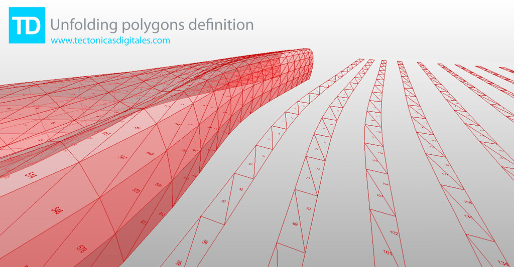
- Added by Francisco Calvo at 11:08am on February 8, 2010
- Comment on: Topic 'Autodesk's world domination'
- Simpsons episode were Bart goes into a mall and in the time he goes in and out of a shop all others have been turned into Starbucks. I personally don't like it but you can't say they are crushing all competitors because, as far as i know, all owners of those software packages voluntarily sold their property for a good price. I would actually be more worried that an antitrust lawsuit was filed against Autodesk. For example, this is what happened with Rockefeller's Standard Oil: The antitrust case against Standard Oil also seems absurd because its share of the petroleum products market had actually dropped significantly over the years. From a high of 88 percent in 1890, Standard Oil's market share had fallen to 64 percent by 1911, the year in which the US Supreme Court reaffirmed the lower court finding that Standard Oil was guilty of monopolizing the petroleum products industry.[32] The court argued, in essence, that Standard Oil was a "large" company with many divisions, and if those divisions were in reality separate companies, there would be more competition. The court made no mention at all of the industry's economic performance; of supposed predatory pricing; of whether industry output had been restrained, as monopoly theory holds; or of any other economic factors relevant to determining harm to consumers. The mere fact that Standard Oil had organized some thirty separate divisions under one consolidated management structure (a trust) was sufficient reason to label it a monopoly and force the company to break up into a number of smaller units. To economists, "predatory pricing" is theoretical nonsense and has no empirical validity, either. In other words, the organizational structure that was responsible for the company's great efficiencies and decades-long price cutting and product improving was seriously damaged. Standard Oil became much less efficient as a result, to the benefit of its less efficient rivals and to the detriment of consumers. From: http://mises.org/daily/2317 (Beware, that site is very ideologically charged)…
- Added by Vicente Soler at 3:57pm on April 28, 2010
- Topic: Multiple Attractors Scaled by Independent Percentage Values
- points within the bounds of the site boundary and use each location as an attractor point controlling a variable at each point in the grid (radius of a circle/height of a cube/colour based on a gradient etc.).This would be based on proximity to the attractor points with the effect of each attractor point essentially scaled by the percentage associated with it. For example a location with 88% visitor rates would have a more dramatic effect than a location with 26% visitor rates. I've had a bit of a play around but can't seem to get beyond the point of what is shown in basic point attractor tutorials online. I'm definitely a novice. Here's how I figured it would be done: 1) Create a grid of source points within a boundary curve. 2) Select 18 pre-defined attractor points. 2) Measure the distance between the source points and the attractor points. 3) Invert this data so that variables increase with proximity rather than decrease. 4) Give each of the attractor points a strength value from 1-100% based on the visitor rates. 5) Use the scaled data to control a variable at each of the source points. 6) Create some way to control the drop-off rate of the effect from each point. It is at step 3 that I get completely lost. I hope my description is clear. Any help would be greatly appreciated, Adam …
- Added by Adam_M at 11:26pm on March 10, 2016
About
Welcome to
Grasshopper
Translate
Search
Photos
Videos
-
Grab Building
Added by Parametric House 0 Comments 0 Likes
-
Kangaroo Mesh
Added by Parametric House 0 Comments 0 Likes
-
Wind Pavilion
Added by Parametric House 0 Comments 0 Likes
© 2024 Created by Scott Davidson.
Powered by
![]()